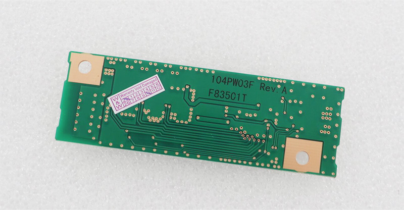
In the intricate world of industrial automation and precision motor control, the inverter stands as a pivotal component, dictating efficiency, reliability, and performance. Among the myriad of models and revisions, the 104PW03F Rev.A Inverter emerges as a specific point of focus for engineers, maintenance technicians, and procurement specialists. This article delves deep into this particular unit, moving beyond basic datasheet parameters to explore its architectural significance, typical applications, and the critical considerations surrounding its operation and lifecycle.
Understanding this component is not merely an exercise in technical specification review. It is about comprehending its role within a larger system, diagnosing its failure modes, and navigating the challenges of maintaining or replacing a defined revision in a fast-evolving technological landscape. Our exploration will systematically unpack the design philosophy behind the 104PW03F Rev.A, its practical implementation, and the strategic knowledge required to manage assets dependent on its function. This journey provides actionable insights for professionals tasked with ensuring operational continuity and optimizing drive system performance.
1 Architectural Design and Core Functionality
The
104PW03F Rev.A Inverter represents a specific generation of power conversion technology, typically designed to control the speed and torque of an AC induction motor by varying the frequency and voltage of its power supply. The "Rev.A" designation is crucial, indicating the first major revision of the base 104PW03F platform. This revision often incorporates foundational fixes, component substitutions for improved reliability, or minor feature enhancements identified after the initial release.
At its heart, the inverter's architecture comprises a rectifier section to convert incoming AC to DC, a DC bus with filtering capacitors, and an intelligent inverter section using IGBTs (Insulated-Gate Bipolar Transistors) to synthesize variable-frequency AC output. The Rev.A iteration would have solidified the choices of key semiconductors, gate drive circuitry, and protection mechanisms. Understanding this base architecture is essential for troubleshooting, as it defines the unit's capabilities, limitations, and inherent points of stress, such as DC bus capacitor aging or IGBT thermal management.
2 Typical Applications and System Integration
This inverter model is commonly deployed in industrial environments requiring robust and precise motor control. Typical applications include conveyor systems, pump and fan control, mixing equipment, and material handling machinery. Its integration is seldom isolated; the
104PW03F Rev.A operates as a subordinate component within a broader control hierarchy.
It receives command signals (e.g., speed reference, start/stop) from a central PLC (Programmable Logic Controller) or a dedicated control panel via analog (0-10V, 4-20mA) or digital communication protocols common at its time of manufacture, such as Modbus. Its successful integration hinges on proper parameterization—configuring motor nameplate data (FLA, voltage), acceleration/deceleration ramps, and current limits to match both the motor and the mechanical process. Misconfiguration here is a leading cause of perceived inverter failure, underscoring the need for thorough setup documentation.
3 Operational Parameters and Performance Optimization
Optimizing the performance of the
104PW03F Rev.A extends beyond basic commissioning. Key operational parameters demand attention for energy efficiency and longevity. The carrier frequency (PWM switching frequency) setting is a prime example: a higher frequency reduces motor noise but increases inverter switching losses and heat generation. Finding the optimal balance is process-dependent.
Furthermore, leveraging features like automatic energy optimization, which adjusts motor flux based on load, can yield significant power savings in variable-torque applications like centrifugal pumps. Proper tuning of the PID loop for closed-loop process control (if used) is also critical. Regularly monitoring operational data—output current relative to rated capacity, heat sink temperature, and DC bus voltage—provides a health baseline and allows for predictive maintenance, preventing unscheduled downtime.
4 Common Failure Modes and Diagnostic Procedures
Despite robust design, inverters are susceptible to specific failure modes. The
104PW03F Rev.A has its common points of vulnerability. DC bus electrolytic capacitors degrade over time, especially in high-temperature environments, leading to loss of capacitance, increased ripple, and eventual inverter shutdown or damage. IGBT modules can fail due to thermal cycling, overcurrent events, or voltage transients from the power line or motor side.
Diagnostic procedures should be methodical. Begin with a visual inspection for bulged capacitors, burnt components, or poor connections. Use a multimeter to check for shorted diodes in the rectifier bridge and shorted IGBTs in the output stage. Before powering the unit, checking the DC bus capacitance and resistance can reveal hidden issues. Understanding the meaning of fault codes (e.g., Overcurrent OC, Overvoltage OV, Ground Fault GF) stored in the inverter's memory is the first and most critical step in isolating the root cause of a failure.
5 Maintenance Strategies for Long-Term Reliability
Proactive maintenance is the key to maximizing the service life of the
104PW03F Rev.AInverter. A comprehensive strategy goes beyond reactive repairs. The cornerstone is thermal management: ensuring cooling fans are operational, air intakes and heat sinks are free of dust and debris, and ambient temperatures are within specification. Periodic tightening of power and control terminal connections is vital to prevent high-resistance contacts that cause localized heating.
For units in critical service, consider periodic preventive replacement of DC bus capacitors, which have a predictable lifespan. Regularly backing up the inverter's parameter set to non-volatile memory or a PC is an often-overlooked but crucial administrative maintenance task. This ensures rapid recovery in the event of a control board failure or full unit replacement, avoiding lengthy recommissioning.
6 Obsolescence Management and Modernization Paths
The "Rev.A" suffix inherently signals a product at a certain stage in its lifecycle. Manufacturers eventually discontinue support for older revisions, leading to challenges in sourcing exact replacement parts or finding technicians familiar with legacy technology. This makes obsolescence management a strategic necessity.
Options typically include:
Seeking Last-Time Buys: Procuring spare units or critical sub-assemblies (like control boards) before manufacturing ceases.
Using Certified Refurbished Units: Sourcing from reputable third-party rebuilders who can provide units with updated components (e.g., new capacitors).
Planning a Modernization: Evaluating a upgrade to a newer inverter platform. This path, while involving higher initial cost and engineering time, offers benefits like enhanced efficiency, advanced connectivity (Ethernet/IP, Profinet), improved diagnostics, and longer-term support.
The choice depends on the criticality of the application, the number of units in operation, and long-term operational goals.
7 FAQs: 104PW03F Rev.A Inverter
Q1: What does "Rev.A" signify in the model number?A1: It indicates the first major revision of the original 104PW03F design, often containing initial performance improvements and component reliability fixes.
Q2: What is the most common cause of failure for this inverter?A2: Degradation and failure of the DC bus electrolytic capacitors, followed by IGBT module failures due to overheating or electrical stress.
Q3: Can I replace a failed 104PW03F Rev.A with a newer Rev.B or Rev.C?A3: Possibly, but it is not always a direct drop-in replacement. Physical dimensions, terminal layouts, and default parameters may differ. Always consult cross-reference guides and the manufacturer.
Q4: How can I optimize this inverter for energy savings?A4> Ensure it is correctly parameterized for your motor, use sensorless vector control if available for better low-speed performance, and enable features like automatic energy optimization for variable torque loads.
Q5: What are the key parameters I must configure during commissioning?A5: Motor nameplate data (full load amps, voltage, base frequency), acceleration/deceleration times, motor overload protection current, and control source (terminal, serial, etc.).
Q6: Where can I find the technical manual or wiring diagram?A6> Documentation is often available from the original equipment manufacturer (OEM) of the machine it's installed in or from the inverter brand's website (if private-labeled, identify the base manufacturer).
Q7: What does a "DC Bus Under voltage" fault typically indicate?A7: This usually points to a problem with the incoming AC power supply (phase loss, low voltage), a failing rectifier section, or excessively discharged DC bus capacitors.
Q8: Is it worth repairing a failed unit, or should I replace it?A8: For a single, non-critical unit with minor damage (e.g., just capacitors), repair by a specialist can be cost-effective. For widespread failures or obsolete units, replacement/modernization should be considered.
Q9: How often should I perform preventive maintenance?A9: Conduct visual and thermal inspections quarterly. Clean heat sinks and check fans every 6-12 months depending on environment. Consider capacitor replacement every 5-7 years in 24/7 operation.
Q10: Can this inverter communicate with a modern SCADA system?A10: It likely uses legacy serial communication (e.g., Modbus RTU). Integration is possible but may require a protocol gateway or converter to interface with modern Ethernet-based SCADA networks.
8 Conclusion
The
104PW03F Rev.A Inverter is more than a part number; it is a functional asset with a defined lifecycle and specific operational profile. A deep understanding of its design, integration, and failure characteristics empowers maintenance and engineering teams to move from a reactive stance to one of proactive management and strategic planning.
Mastering its parameters optimizes performance, while recognizing its common failure modes enables swift diagnosis and repair. Ultimately, the most critical insight may be recognizing when continued support for a legacy revision becomes a business risk, prompting a well-planned transition to modern technology. In the relentless pursuit of industrial efficiency and uptime, such comprehensive knowledge of key components like the 104PW03F Rev.A is indispensable.