- Industrial LCD display
-
Industrial Products
- DC Servo Drive
- AC Servo Drive
- other
- Heidelberg
- FANUC
- IFM
- Meter
- CCD
- Membrane Keypad
- Film
- YOKOGAWA Module
- Card
- ABB
- MITSUBISHI
- FANUC
- KEYENCE
- BECKHOFF
- Honeywell
- HOLLYSYS
- FUJI servo drives
- HP
- solenoid valve
- thermostat
- Siemens adapter
- color oscilloscope
- Fujitsu connector
- CHELIC
- SMC
- CISCO Module
- INTEL
- Key board
- FAIRCHILD
- Motherboard
- Board
- Bearing
- other
- Control Panel
- Contactor
- Circuit
- OMRON
- Relay
- Controller
- Photoelectric Switch
- Photoelectric Sensor
- Original
- Fan
- Motor Driver
- Limit Switch
- Amplifier
- power supply
- LENZE
- Cable
- Encoder
- Sensor
- Transformer
- Fiber Optic Sensor
- Protection Relay
- Temperature Controller
- Proximity Switch
- Switch Sensor
- Siemens
- Industrial board
- HMI Touch Glass
-
HMI Full Machine Whole unit
- OMRON HMI Touch Panel
- Siemens HMI Touch Panel
- Mitsubishi HMI Touch Panel
- Allen-Bradley automation HMI Touch Panel
- DELTA HMI Touch Panel
- EVIEW DELTA HMI Touch Panel
- KINCO DELTA HMI Touch Panel
- HITECH HMI Touch Panel
- WEINTECK HMI Touch Panel
- TECVIEW HMI Touch Panel
- WEINVIEW HMI Touch Panel
- PRO-FACE HMI Touch Panel
- SIMATIC HMI Touch Panel
- AMPIRE HMI Touch Panel
- HEIDELBERG HMI Touch Panel
- PANASONIC HMI Touch Panel
- PATLITE HMI Touch Panel
- KYOCERA HMI Touch Panel
- KEYENCE HMI Touch Panel
- WEINVIEW HMI Touch Panel
- HITECH HMI Touch Panel
- FUJI HMI Touch Panel
- HAKKO HMI Touch Panel
- SCHNEIDER HMI Touch Panel
- SAMKOON touch panel
- other
- Module
- lcd inverter
- Membrane Keypad Switch
- Winni Touch Screens
- Frequency Inverter
- Servo Motor
- PLC


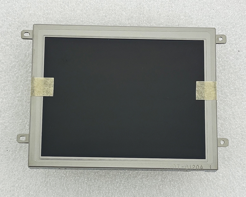
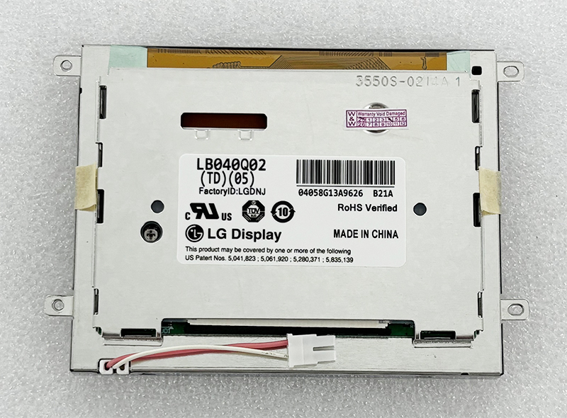
LB040Q02-TD05 4.0 inch 320*240 LCD PANEL MONITOR
In the sprawling ecosystem of industrial electronics, consumer appliances, and embedded systems, the display panel often serves as the primary human-machine interface (HMI). While large, high-resolution screens dominate the consumer market, a distinct class of compact, ruggedized displays powers the critical applications behind the scenes. The LB040Q02-TD05, a 4.0-inch TFT LCD panel with a native resolution of 320×240 pixels (QVGA), represents this niche. It is not designed for cinematic immersion; rather, it is engineered for clarity, durability, and functional reliability.
This article delves deep into the specifications, technological constraints, and real-world utility of this specific panel. We will dissect why the QVGA resolution remains relevant in a 4K world, explore its interface requirements (typically 24-bit RGB parallel), and analyze its performance characteristics in demanding environments. For engineers, procurement specialists, and hobbyists involved in display integration or system maintenance, understanding the LB040Q02-TD05 is not about chasing trends—it is about mastering the fundamentals of functional display design. This guide will provide a comprehensive roadmap to its capabilities and limitations.
At first glance, a 320x240 pixel count on a 4.0-inch diagonal seems anachronistic. Modern smartphones boast pixel densities that make individual pixels invisible. However, the engineering reality is that QVGA (Quarter Video Graphics Array) offers a distinct advantage in system efficiency and cost optimization. The LB040Q02-TD05 leverages this resolution to minimize data bandwidth required from the host controller. This is crucial for embedded systems using low-cost microcontrollers (MCUs) or FPGAs that lack the memory bandwidth to drive higher resolutions fluidly.
The pixel density, while low by consumer standards (~100 PPI), is perfectly adequate for displaying text, simple icons, and live data readouts from a distance of 30-50cm. The 4:3 aspect ratio is also inherently better suited for data-centric applications—like showing a list of parameters or a waveform—than the 16:9 format, which wastes vertical space. Furthermore, the lower resolution significantly reduces the cost of the driving logic and the LCD glass itself. In a world obsessed with fidelity, the LB040Q02-TD05 prioritizes functionality, speed, and cost control, making it the optimal choice for industrial panels, medical device readouts, and point-of-sale terminals where simple, reliable communication is paramount.
The LB040Q02-TD05 typically utilizes a 24-bit parallel RGB interface, a standard that defines how the display receives its visual data. This interface is technically demanding but offers low latency. It requires a dedicated set of signal lines: 8 bits for Red, 8 bits for Green, and 8 bits for Blue, alongside synchronization signals (VSYNC, HSYNC, DE) and a pixel clock (CLK). This architecture allows for direct memory mapping of the display frame buffer, enabling rapid updates without complex serial decoding.
Understanding this interface is critical. It means the panel is not a plug-and-play USB monitor. It is a component that requires a compatible controller (a processor with a parallel LCD controller or an FPGA) to generate the correct timing diagrams. The timing parameters—such as horizontal blanking, vertical back porch, and pixel clock frequency (typically in the range of 6-10 MHz for QVGA)—are factory-configured and must be meticulously replicated by the host system. A 5% deviation in clock speed can result in image tearing or total display failure. For engineers, this section underscores the importance of reading the specific datasheet for the LB040Q02-TD05 revision used.
The optical characteristics of the LB040Q02-TD05 are tailored for controlled environments, not direct sunlight. Typical specifications include a brightness of 250-350 cd/m² (nits) and a contrast ratio of approximately 500:1. While these figures are modest compared to modern IPS panels, they are highly competitive for TN (Twisted Nematic) technology, which is common in this class of display. The TN technology has a significant trade-off: limited viewing angles.
Viewing angles for the LB040Q02-TD05 are typically quoted at 60° / 60° (L/R) and 40° / 60° (U/D). This means the image quality degrades noticeably when viewed from an angle, especially vertically. Color inversion (where blacks turn white) is common beyond these limits. This is not a flaw; it is a design choice. TN panels offer faster response times (often 10-15ms) and lower power consumption than IPS panels of the same era. For applications where the operator sits directly in front of the screen, such as a laboratory instrument or a printer control panel, these optical limits are perfectly acceptable. The panel is optimized for on-axis clarity and low power draw.
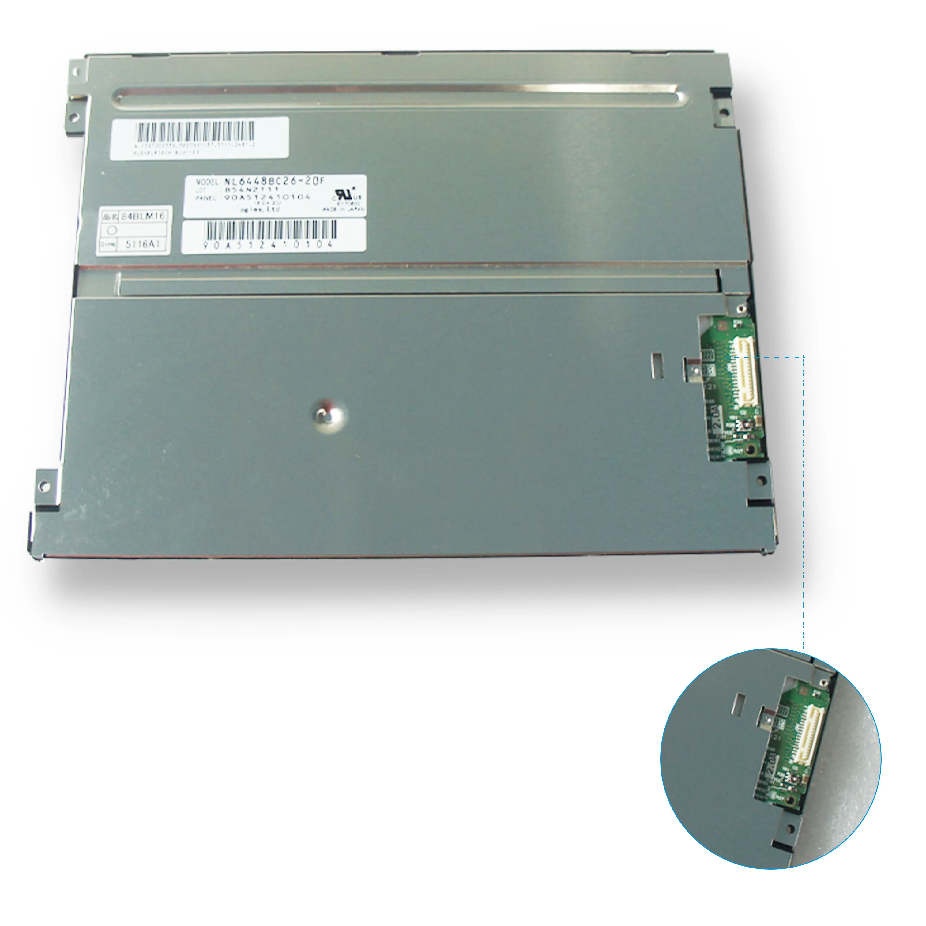
Integrating the LB040Q02-TD05 into a product is a non-trivial task requiring attention to detail. The first challenge is the physical connector. This panel usually utilizes a fine-pitch FPC (Flexible Printed Circuit) connector, often a 40-pin or 50-pin part (e.g., JAE or Hirose type). The pitch is typically 0.5mm, demanding careful handling and alignment on the PCB. The second challenge is the backlight. It is almost certainly an LED array (White LED) requiring a constant current driver. A simple series resistor will not suffice; a proper boost converter or linear current sink is needed to provide the specified forward current (often 20-40mA per string) to achieve rated brightness.
Power consumption is another critical factor. The panel itself requires 3.3V for logic (for the T-con) and a separate voltage for the source driver (typically 10V-15V), often generated by an on-board DC-DC converter or provided externally. The total system power, including backlight, is typically between 1.5W and 2.5W. System designers must ensure the power supply is clean and free of ripple, as noise on the logic or driver lines will manifest as visible artifacts on the screen. Proper ESD protection on the interface lines is also mandatory for industrial reliability.
When evaluating the LB040Q02-TD05, one must consider modern alternatives like the 4-inch IPS panels with higher resolution (480x800). The IPS panel offers vastly superior viewing angles and color reproduction but comes with penalties. It requires a faster clock rate (pushing 40-50 MHz), consumes more power, and the cost of the glass and driver IC is significantly higher. For a simple numeric or text display, this is overkill.
Another competitor is the OLED 4-inch panel. While offering perfect blacks and high contrast, OLEDs suffer from burn-in in static HMI applications (like a factory timer or a logo) and have a shorter lifespan in high-brightness environments. The LB040Q02-TD05, being an LCD, is inherently immune to burn-in and has a typical operational lifespan of 30,000-50,000 hours. This makes it superior for 24/7 operation in security systems or medical equipment. The choice boils down to a trade-off: image quality and viewing angle (modern IPS) vs. cost, simplicity, and long-term reliability (LB040Q02-TD05). For many industrial designers, the latter wins.
The most common point of failure in the LB040Q02-TD05 is the LED backlight. Over time, the LEDs experience lumen depreciation. After 30,000 hours, the display may be 30-50% dimmer than when new. This is not a failure of the LCD itself, but of the light source. The good news is that the backlight can often be replaced by sourcing a specific LED strip compatible with the panel's light guide. This is a complex task requiring a hot-air soldering station, but it extends the panel's life significantly.
The second issue is the logic board / T-con board. If the display shows vertical lines, garbled patterns, or no image, the controller IC on the attached flex cable is likely damaged by an ESD event or voltage spike. Unfortunately, this board is often integral to the panel and cannot be repaired easily. In such cases, the entire LB040Q02-TD05 module must be replaced. To maximize lifespan, it is essential to use a proper power sequence (VCC on, then backlight on; backlight off, then VCC off) and to place the display in a clean, vibration-free environment. Thermal management (keeping the panel below 60°C) is also critical for preventing pixel aging and polarizer degradation.
Q: What is the native resolution of the LB040Q02-TD05?
A: The native resolution is 320 x 240 pixels (QVGA).
Q: Is this display a touch screen?
A: Typically, the LB040Q02-TD05 is a raw LCD panel without integrated touch. A separate touch sensor layer would be needed.
Q: What interface does it use?
A: It uses a 24-bit parallel RGB interface (8 bits per color), requiring VSYNC, HSYNC, DE, and CLK signals.
Q: Can I use it with an Arduino?
A: Yes, but you need a powerful Arduino board (like the Due or a Teensy) with enough pins for the parallel interface, plus a level shifter for 3.3V logic.
Q: What is the typical power consumption?
A: Approximately 1.8W to 2.2W depending on backlight brightness.
Q: Is the backlight replaceable?
A: Yes, the LED backlight can be replaced with careful soldering, but the LCD glass itself is difficult to replace outside of a factory.
Q: What is the viewing angle?
A: Typical TN panel viewing angles: 60° left/right, 40° up/60° down.
Q: Why does my screen show white lines?
A: This often indicates a connector issue (loose FPC) or a damaged driver IC on the panel's flex cable.
Q: Is this panel suitable for outdoor use in sunlight?
A: Not without significant supplemental lighting. Its 250-350 nits brightness is too dim for direct sunlight.
Q: What voltage does the logic require?
A: The logic voltage is typically 3.3V. The backlight requires a separate constant current supply.
Conclusion: A Legacy of Practicality
The LB040Q02-TD05 4.0-inch 320x240 LCD panel is a testament to the principle that technology does not need to be cutting-edge to be valuable. In an industry flooded with high-resolution, multimedia-centric displays, this panel stands out for its simplicity, reliability, and cost-effectiveness. It serves as the silent interface for countless machines, instruments, and controllers that form the backbone of our industrial and commercial infrastructure.